Yes—wind and solar can be the main sources of electric power if HVDV is used to transport the electricity.
By Emily J. Gertz | Takepart.com 8 hours ago
Coal-fired power plants are the biggest emitters of greenhouse gases in the United States, but new research finds that existing technology could cheaply slash the nation’s carbon spew nearly 80 percent by 2030.
How? By transporting renewable energy from where the sun is shining and the wind is blowing to where it is not, according to the study, which was published on Monday in the journal Nature Climate Change by scientists from the National Oceanic and Atmospheric Administration and the University of Colorado Boulder.
NOAA’s highly detailed weather data shows there’s nearly always someplace in the 48 contiguous states where electricity can be generated by solar power stations and wind farms, even if it happens to be hundreds or thousands of miles away from where it’s needed.
The quandary: How to move electricity generated by that sun or wind over long distances without losing too much of it in the process.
The solution: A proven technology, called high-voltage direct current, already exists and can carry power across long distances more efficiently than alternating current, the standard power transmission mode in the U.S.
Utilities could add direct-current infrastructure to alternating-current transmission lines over the next 15 years as part of planned updates and upgrades without breaking the bank, said study coauthor Alexander MacDonald, who recently retired as director of NOAA’s Earth System Research Laboratory.
“Almost everybody believes that if we go to wind and solar energy it will be more expensive, or won’t be ready unless we have a big technological breakthrough” in battery storage technology, MacDonald said. “Our study says that with existing transmission technology and use of the whole 48 states with this ‘interstate for electrons,’ we’re ready right now to have a national system that has the same electric costs as today, with as much as 80 percent less carbon, and just as reliable.”
The greater reliance on wind and solar power would also cut water use for energy by 65 percent, the study found. That’s because fossil fuel plants, which generate 40 percent of the nation’s carbon emissions, need large volumes of water for cooling.
“Our study assumed that the existing U.S. power system, with all of its AC distribution and usage, stays the same,” said MacDonald. “Power can be taken off the HVDC network for use, and put on by generation. To a power provider, let’s say a utility, instead of building a coal plant, they build a connection to the HVDC network. Everything else stays the same.”
To test ideas about the most cost-effective means of generating power, MacDonald and his colleagues conducted a complex mathematical analysis that combined finely detailed data on continent-wide weather patterns from 2006 to 2008 with equally detailed data on power demand for the same period.
“NOAA folks have known for some time how big weather is,” said mathematician and physicist Christopher Clack of the Cooperative Institute for Research in Environmental Sciences, a collaboration between NOAA and the University of Colorado Boulder. “We built and ran a very sophisticated model that was able to take advantage of [NOAA’s] exceptionally good-quality weather data to look at the situation of the grid, and see if there’s any way of running the grid that would incorporate a really cheap system.”
The model was not designed to prioritize low carbon emissions, he said. “We tried to be completely agnostic on which technologies were picked. It turned out the most effective combination we saw was full U.S., 48-state transmission, backed up by gas when solar and wind wasn’t enough.”
Using the U.S. Energy Information Administration’s estimate of a 0.7 percent increase in power demand annually between 2015 and 2030, the researchers found that scenarios combining wind, solar, and natural gas power with a nationwide transmission grid cut greenhouse gas emissions from 33 to 78 percent below 1990 levels.
If gas was cheaper than solar and wind, the emissions were higher; when renewables beat gas on price, emissions went down.
The cost to ratepayers was between $0.086 and $0.10 per kilowatt-hour—comparable to the actual average nationwide cost of $0.094 per kilowatt-hour in 2015 and potentially saving power customers $47.2 billion a year.
If coal-fired power was added to the mix, the cost of power dropped by just one one-thousandth of a cent, to $0.085 per kilowatt-hour. But greenhouse gas emissions went up, to 37 percent over 1990 levels.
Writing in the same issue of Nature Climate Change, Mark Jacobson, an environmental engineer at Stanford University, noted a few limitations to the study.
“Whereas the model optimizes resource location based on cost and considers several types of land use limitations, it also does not consider societal constraints on areas of beauty that might prevent development in some of the proposed locations,” he wrote. “Future work on this topic may also benefit from considering storage to eliminate the remainder of CO2 emissions.”
But Jacobson concluded that without a single new technology, “the study pushes the envelope to show that intermittent renewables plus transmission can eliminate most fossil fuel electricity while matching power demand at lower cost than a fossil-fuel-based grid.”
At the recent climate accord talks in Paris, the U.S. committed to lowering its greenhouse gas emissions 28 percent below 2005 levels by 2025.
According to NOAA, the new study’s findings show that the U.S. could cut its emissions 31 percent below 2005 levels within 15 years solely with changes in electricity generation.
Above is from: http://news.yahoo.com/u-could-fast-cheap-switch-clean-energy-160005301.html
************************************************************************************************************************************************************************

High-voltage direct current
From Wikipedia, the free encyclopedia

Long distance HVDC lines carrying hydroelectricity from Canada's Nelson river to this converter station where it is converted to AC for use in southern Manitoba's grid
A high-voltage, direct current (HVDC) electric power transmission system (also called a power super highway or an electrical super highway)[1][2][3][4][5] uses direct current for the bulk transmission of electrical power, in contrast with the more common alternating current (AC) systems.[6] For long-distance transmission, HVDC systems may be less expensive and suffer lower electrical losses. For underwater power cables, HVDC avoids the heavy currents required to charge and discharge the cable capacitance each cycle. For shorter distances, the higher cost of DC conversion equipment compared to an AC system may still be justified, due to other benefits of direct current links.
HVDC allows power transmission between unsynchronized AC transmission systems. Since the power flow through an HVDC link can be controlled independently of the phase angle between source and load, it can stabilize a network against disturbances due to rapid changes in power. HVDC also allows transfer of power between grid systems running at different frequencies, such as 50 Hz and 60 Hz. This improves the stability and economy of each grid, by allowing exchange of power between incompatible networks.
The modern form of HVDC transmission uses technology developed extensively in the 1930s in Sweden (ASEA) and in Germany. Early commercial installations included one in the Soviet Union in 1951 between Moscow and Kashira, and a 100 kV, 20 MW system between Gotland and mainland Sweden in 1954.[7] The longest HVDC link in the world is the Rio Madeira link in Brazil, which consists of two bipoles of ±600 kV, 3150 MW each, connecting Porto Velho in the state of Rondônia to the São Paulo area. The length of the DC line is 2,375 km (1,476 mi).[8]
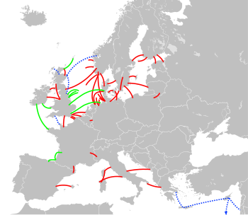
Existing links
Under construction
Proposed
Many of these transfer power from renewable sources such as hydro and wind. For names, see also the annotated version.
Contents
[
hide]
High voltage transmission[edit]
High voltage is used for electric power transmission to reduce the energy lost in the resistance of the wires. For a given quantity of power transmitted, doubling the voltage will deliver the same power at only half the current. Since the power lost as heat in the wires is proportional to the square of the current for a given conductor size, but does not depend on the voltage, doubling the voltage reduces the line losses per unit of electrical power delivered by a factor of 4. While power lost in transmission can also be reduced by increasing the conductor size, larger conductors are heavier and more expensive.
High voltage cannot readily be used for lighting or motors, so transmission-level voltages must be reduced for end-use equipment. Transformers are used to change the voltage levels in alternating current (AC) transmission circuits. Because transformers made voltage changes practical, and AC generators were more efficient than those using DC, AC became dominant after the introduction of practical systems of distribution in Europe in 1891[9] and the conclusion in 1892 of the War of Currents, a competition being fought on many fronts in the US between the DC system of Thomas Edison and the AC system of George Westinghouse.[10]
Practical conversion of power between AC and DC became possible with the development of power electronics devices such as mercury-arc valves and, starting in the 1970s, semiconductor devices as thyristors, integrated gate-commutated thyristors (IGCTs), MOS-controlled thyristors (MCTs) and insulated-gate bipolar transistors (IGBT).[11]
History of HVDC technology[edit]
Electromechanical (Thury) systems[edit]
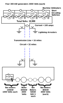
Schematic diagram of a Thury HVDC transmission system

HVDC in 1971: this 150 kV mercury-arc valve converted AC hydropower voltage for transmission to distant cities from Manitoba Hydro generators.

Bipolar system pylons of the Baltic Cable HVDC in Sweden
The first long-distance transmission of electric power was demonstrated using direct current in 1882 at Miesbach-Munich Power Transmission, but only 1.5 kW was transmitted.[12] An early method of high-voltage DC transmission was developed by the Swiss engineer René Thury[13] and his method was put into practice by 1889 in Italy by the Acquedotto De Ferrari-Galliera company. This system used series-connected motor-generator sets to increase the voltage. Each set was insulated from electrical ground and driven by insulated shafts from a prime mover. The transmission line was operated in a 'constant current' mode, with up to 5,000 volts across each machine, some machines having double commutators to reduce the voltage on each commutator. This system transmitted 630 kW at 14 kV DC over a distance of 120 km.[14][15] The Moutiers–Lyon system transmitted 8,600 kW of hydroelectric power a distance of 200 km, including 10 km of underground cable. This system used eight series-connected generators with dual commutators for a total voltage of 150,000 volts between the positive and negative poles, and operated from c.1906 until 1936. Fifteen Thury systems were in operation by 1913.[16] Other Thury systems operating at up to 100 kV DC worked into the 1930s, but the rotating machinery required high maintenance and had high energy loss. Various other electromechanical devices were tested during the first half of the 20th century with little commercial success.[17]
One technique attempted for conversion of direct current from a high transmission voltage to lower utilization voltage was to charge series-connected batteries, then reconnect the batteries in parallel to serve distribution loads.[18] While at least two commercial installations were tried around the turn of the 20th century, the technique was not generally useful owing to the limited capacity of batteries, difficulties in switching between series and parallel connections, and the inherent energy inefficiency of a battery charge/discharge cycle.
Mercury arc valves[edit]
First proposed in 1914,[19] the grid controlled mercury-arc valve became available for power transmission during the period 1920 to 1940. Starting in 1932, General Electric tested mercury-vapor valves and a 12 kV DC transmission line, which also served to convert 40 Hz generation to serve 60 Hz loads, at Mechanicville, New York. In 1941, a 60 MW, ±200 kV, 115 km buried cable link was designed for the city of Berlin using mercury arc valves (Elbe-Project), but owing to the collapse of the German government in 1945 the project was never completed.[20] The nominal justification for the project was that, during wartime, a buried cable would be less conspicuous as a bombing target. The equipment was moved to the Soviet Union and was put into service there as the Moscow–Kashira HVDC system.[21] The Moscow–Kashira system and the 1954 connection by Uno Lamm's group at ASEA between the mainland of Sweden and the island of Gotland marked the beginning of the modern era of HVDC transmission.[12]
Mercury arc valves require an external circuit to force the current to zero and thus turn off the valve. In HVDC applications, the AC power system itself provides the means of commutating the current to another valve in the converter. Consequently, converters built with mercury arc valves are known as line-commutated converters (LCC). LCCs require rotating synchronous machines in the AC systems to which they are connected, making power transmission into a passive load impossible.
Mercury arc valves were common in systems designed up to 1972, the last mercury arc HVDC system (the Nelson River Bipole 1 system in Manitoba, Canada) having been put into service in stages between 1972 and 1977.[22] Since then, all mercury arc systems have been either shut down or converted to use solid state devices. The last HVDC system to use mercury arc valves was the Inter-Island HVDC link between the North and South Islands of New Zealand, which used them on one of its two poles. The mercury arc valves were decommissioned on 1 August 2012, ahead of commissioning of replacement thyristor converters.
Thyristor valves[edit]
Since 1977, new HVDC systems have used only solid-state devices, in most cases thyristor valves. Like mercury arc valves, thyristors require connection to an external AC circuit in HVDC applications to turn them on and off. HVDC using thyristor valves is also known as line-commutated converter (LCC) HVDC.
Development of thyristor valves for HVDC began in the late 1960s. The first complete HVDC scheme based on thyristor valves was the Eel River scheme in Canada, which was built by General Electric and went into service in 1972.
On March 15, 1979, a 1920 MW thyristor based direct current connection between Cabora Bassa and Johannesburg (1,410 km) was energised. The conversion equipment was built in 1974 by AEG, and BBC (Brown Boveri Company) and Siemens were partners in the project, the late completion date a result of the civil war.[citation needed] The transmission voltage of ±533 kV was the highest in the world at the time.[12]
Capacitor-commutated converters (CCC)[edit]
Line-commutated converters have some limitations in their use for HVDC systems. This results from requiring the AC circuit to turn off the thyristor current and the need for a short period of 'reverse' voltage to effect the turn-off (turn-off time). An attempt to address these limitations is the Capacitor-Commutated Converter (CCC) which has been used in a small number of HVDC systems. The CCC differs from a conventional HVDC system in that it has series capacitors inserted into the AC line connections, either on the primary or secondary side of the converter transformer. The series capacitors partially offset the commutating inductance of the converter and help to reduce fault currents. This also allows a smaller extinction angle to be used with a converter/inverter, reducing the need for reactive power support. However, CCC has remained only a niche application because of the advent of voltage-source converters (VSC) which completely eliminate the need for an extinction (turn-off) time.
Voltage-source converters (VSC)[edit]
Widely used in motor drives since the 1980s, voltage-source converters started to appear in HVDC in 1997 with the experimental Hellsjön–Grängesberg project in Sweden. By the end of 2011, this technology had captured a significant proportion of the HVDC market.
The development of higher rated insulated-gate bipolar transistors (IGBTs), gate turn-off thyristors (GTOs) and integrated gate-commutated thyristors (IGCTs), has made smaller HVDC systems economical. The manufacturer ABB Group calls this concept HVDC Light, while Siemens calls a similar concept HVDC PLUS (Power Link Universal System) and Alstom call their product based upon this technology HVDC MaxSine. They have extended the use of HVDC down to blocks as small as a few tens of megawatts and lines as short as a few score kilometres of overhead line. There are several different variants of VSC technology: most installations built until 2012 use pulse width modulation in a circuit that is effectively an ultra-high-voltage motor drive. Current installations, including HVDC PLUS and HVDC MaxSine, are based on variants of a converter called a Modular Multi-Level Converter (MMC).
Multilevel converters have the advantage that they allow harmonic filtering equipment to be reduced or eliminated altogether. By way of comparison, AC harmonic filters of typical line-commutated converter stations cover nearly half of the converter station area.
With time, voltage-source converter systems will probably replace all installed simple thyristor-based systems, including the highest DC power transmission applications.[11]
Advantages of HVDC over AC transmission[edit]
A long distance point to point HVDC transmission scheme generally has lower overall investment cost and lower losses than an equivalent AC transmission scheme. HVDC conversion equipment at the terminal stations is costly, but the total DC transmission line costs over long distances are lower than AC line of the same distance. HVDC requires less conductor per unit distance than an AC line, as there is no need to support three phases and there is no skin effect.
Depending on voltage level and construction details, HVDC transmission losses are quoted as about 3.5% per 1,000 km, which are 30 – 40% less than with AC lines, at the same voltage levels.[23] This is because direct current transfers only active power and thus causes lower losses than alternating current, which transfers both active and reactive power.
HVDC transmission may also be selected for other technical benefits. HVDC can transfer power between separate AC networks. HVDC powerflow between separate AC systems can be automatically controlled to support either network during transient conditions, but without the risk that a major power system collapse in one network will lead to a collapse in the second. HVDC improves on system controllability, with at least one HVDC link embedded in an AC grid—in the deregulated environment, the controllability feature is particularly useful where control of energy trading is needed.
The combined economic and technical benefits of HVDC transmission can make it a suitable choice for connecting electricity sources that are located far away from the main users.
Specific applications where HVDC transmission technology provides benefits include:
- Undersea cables transmission schemes (e.g., 250 km Baltic Cable between Sweden and Germany,[24] the 580 km NorNed cable between Norway and the Netherlands,[25] and 290 km Basslink between the Australian mainland and Tasmania[26]).
- Endpoint-to-endpoint long-haul bulk power transmission without intermediate 'taps', usually to connect a remote generating plant to the main grid, for example the Nelson River DC Transmission System in Canada.
- Increasing the capacity of an existing power grid in situations where additional wires are difficult or expensive to install.
- Power transmission and stabilization between unsynchronised AC networks, with the extreme example being an ability to transfer power between countries that use AC at different frequencies. Since such transfer can occur in either direction, it increases the stability of both networks by allowing them to draw on each other in emergencies and failures.
- Stabilizing a predominantly AC power-grid, without increasing fault levels (prospective short circuit current).
- Integration of renewable resources such as wind into the main transmission grid. HVDC overhead lines for onshore wind integration projects and HVDC cables for offshore projects have been proposed in North America and Europe for both technical and economic reasons. DC grids with multiple voltage-source converters (VSCs) are one of the technical solutions for pooling offshore wind energy and transmitting it to load centers located far away onshore.[27]
Cable systems[edit]
Long undersea / underground high-voltage cables have a high electrical capacitance compared with overhead transmission lines, since the live conductors within the cable are surrounded by a relatively thin layer of insulation (the dielectric), and a metal sheath. The geometry is that of a long co-axial capacitor. The total capacitance increases with the length of the cable. This capacitance is in a parallel circuit with the load. Where alternating current is used for cable transmission, additional current must flow in the cable to charge this cable capacitance. This extra current flow causes added energy loss via dissipation of heat in the conductors of the cable, raising its temperature. Additional energy losses also occur as a result of dielectric losses in the cable insulation.
However, if direct current is used, the cable capacitance is charged only when the cable is first energized or if the voltage level changes; there is no additional current required. For a sufficiently long AC cable, the entire current-carrying ability of the conductor would be needed to supply the charging current alone. This cable capacitance issue limits the length and power carrying ability of AC powered cables. DC powered cables are limited only by their temperature rise and Ohm's Law. Although some leakage current flows through the dielectric insulator, this is small compared to the cable's rated current.
Overhead line systems[edit]
The capacitive effect of long underground or undersea cables in AC transmission applications also applies to AC overhead lines, although to a much lesser extent. Nevertheless, for a long AC overhead transmission line, the current flowing just to charge the line capacitance can be significant, and this reduces the capability of the line to carry useful current to the load at the remote end. Another factor that reduces the useful current carrying ability of AC lines is the skin effect, which causes a non-uniform distribution of current over the cross-sectional area of the conductor. Transmission line conductors operating with direct current do not suffer from either of these constraints. Therefore, for the same conductor losses (or heating effect), a given conductor can carry more current to the load when operating with HVDC than AC.
Finally, depending upon the environmental conditions and the performance of overhead line insulation operating with HVDC, it may be possible for a given transmission line to operate with a constant HVDC voltage that is approximately the same as the peak AC voltage for which it is designed and insulated. The power delivered in an AC system is defined by the root mean square (RMS) of an AC voltage, but RMS is only about 71% of the peak voltage. Therefore, if the HVDC line can operate continuously with an HVDC voltage that is the same as the peak voltage of the AC equivalent line, then for a given current (where HVDC current is the same as the RMS current in the AC line), the power transmission capability when operating with HVDC is approximately 40% higher than the capability when operating with AC.
Asynchronous connections[edit]
Because HVDC allows power transmission between unsynchronized AC distribution systems, it can help increase system stability, by preventing cascading failures from propagating from one part of a wider power transmission grid to another. Changes in load that would cause portions of an AC network to become unsynchronized and to separate, would not similarly affect a DC link, and the power flow through the DC link would tend to stabilize the AC network. The magnitude and direction of power flow through a DC link can be directly controlled, and changed as needed to support the AC networks at either end of the DC link. This has caused many power system operators to contemplate wider use of HVDC technology for its stability benefits alone.
Disadvantages[edit]
The disadvantages of HVDC are in conversion, switching, control, availability and maintenance.
HVDC is less reliable and has lower availability than alternating current (AC) systems, mainly due to the extra conversion equipment. Single-pole systems have availability of about 98.5%, with about a third of the downtime unscheduled due to faults. Fault-tolerant bipole systems provide high availability for 50% of the link capacity, but availability of the full capacity is about 97% to 98%.[28]
The required converter stations are expensive and have limited overload capacity. At smaller transmission distances, the losses in the converter stations may be bigger than in an AC transmission line for the same distance. The cost of the converters may not be offset by reductions in line construction cost and lower line loss.
Operating a HVDC scheme requires many spare parts to be kept, often exclusively for one system, as HVDC systems are less standardized than AC systems and technology changes faster.
In contrast to AC systems, realizing multiterminal systems is complex (especially with line commutated converters), as is expanding existing schemes to multiterminal systems. Controlling power flow in a multiterminal DC system requires good communication between all the terminals; power flow must be actively regulated by the converter control system instead of relying on the inherent impedance and phase angle properties of an AC transmission line.[29] Multi-terminal systems are rare. As of 2012 only two are in service: the Hydro Québec – New England transmission between Radisson, Sandy Pond and Nicolet[30] and the Sardinia–mainland Italy link which was modified in 1989 to also provide power to the island of Corsica.[31]
HVDC circuit breakers are difficult to build because some mechanism must be included in the circuit breaker to force current to zero, otherwise arcing and contact wear would be too great to allow reliable switching. In November 2012, ABB announced development of the world's first HVDC circuit breaker.[32][33]
The ABB breaker contains four switching elements, two mechanical (one high-speed and one low-speed) and two semiconductor (one high-voltage and one low-voltage). Normally, power flows through the low-speed mechanical switch, the high-speed mechanical switch and the low-voltage semiconductor switch. The last two switches are paralleled by the high-voltage semiconductor switch.
Initially, all switches are closed (on). Because the high-voltage semiconductor switch has much greater resistance than the mechanical switch plus the low-voltage semiconductor switch, current flow through it is low. To disconnect, first the low-voltage semiconductor switch opens. This diverts the current through the high-voltage semiconductor switch. Because of its relatively high resistance, it begins heating very rapidly. Then the high-speed mechanical switch is opened. Unlike the low-voltage semiconductor switch, which is capable of standing off only the voltage drop of the closed high-voltage semiconductor switch, this one is capable of standing off the full voltage. Because no current is flowing through this switch when it opens, it is not damaged by arcing. Then, the high-voltage semiconductor switch is opened. This actually cuts the power. However, it is not quite 100% off. A final low-speed mechanical switch disconnects the residual current.[33]
Costs of high voltage DC transmission[edit]
Generally, providers of HVDC systems, such as Alstom, Siemens and ABB, do not specify cost details of particular projects. It may be considered a commercial matter between the provider and the client.
Costs vary widely depending on the specifics of the project (such as power rating, circuit length, overhead vs. cabled route, land costs, and AC network improvements required at either terminal). A detailed comparison of DC vs. AC transmission costs may be required in situations where there is no clear technical advantage to DC, and economical reasoning alone drives the selection.
However, some practitioners have provided some information:
For an 8 GW 40 km link laid under the English Channel, the following are approximate primary equipment costs for a 2000 MW 500 kV bipolar conventional HVDC link (exclude way-leaving, on-shore reinforcement works, consenting, engineering, insurance, etc.)
- Converter stations ~£110M (~€120M or $173.7M)
- Subsea cable + installation ~£1M/km (~€1.2M or ~$1.6M/km)
So for an 8 GW capacity between England and France in four links, little is left over from £750M for the installed works. Add another £200–300M for the other works depending on additional onshore works required.[34]
An April 2010 announcement for a 2,000 MW, 64 km line between Spain and France is estimated at €700 million. This includes the cost of a tunnel through the Pyrenees.[35]
The conversion process[edit]
Converter[edit]
Main article: HVDC converter
At the heart of an HVDC converter station, the equipment which performs the conversion between AC and DC is referred to as the converter. Almost all HVDC converters are inherently capable of converting from AC to DC (rectification) and from DC to AC (inversion), although in many HVDC systems, the system as a whole is optimised for power flow in only one direction. Irrespective of how the converter itself is designed, the station which is operating (at a given time) with power flow from AC to DC is referred to as the rectifier and the station which is operating with power flow from DC to AC is referred to as the inverter.
Early HVDC systems used electromechanical conversion (the Thury system) but all HVDC systems built since the 1940s have used electronic (static) converters. Electronic converters for HVDC are divided into two main categories:
- Line-commutated converters (LCC)
- Voltage-sourced converters, or current-source converters.
Line-commutated converters[edit]
Most of the HVDC systems in operation today are based on line-commutated converters.
The basic LCC configuration uses a three-phase bridge rectifier or six-pulse bridge, containing six electronic switches, each connecting one of the three phases to one of the two DC rails. A complete switching element is usually referred to as a valve, irrespective of its construction. However, with a phase change only every 60°, considerable harmonic distortion is produced at both the DC and AC terminals when this arrangement is used.

A twelve-pulse bridge rectifier
An enhancement of this arrangement uses 12 valves in a twelve-pulse bridge. The AC is split into two separate three phase supplies before transformation. One of the sets of supplies is then configured to have a star (wye) secondary, the other a delta secondary, establishing a 30° phase difference between the two sets of three phases. With twelve valves connecting each of the two sets of three phases to the two DC rails, there is a phase change every 30°, and harmonics are considerably reduced. For this reason the twelve-pulse system has become standard on most line-commutated converter HVDC systems built since the 1970s.
With line commutated converters, the converter has only one degree of freedom – the firing angle, which represents the time delay between the voltage across a valve becoming positive (at which point the valve would start to conduct if it were made from diodes) and the thyristors being turned on. The DC output voltage of the converter steadily becomes less positive as the firing angle is increased: firing angles of up to 90° correspond to rectification and result in positive DC voltages, while firing angles above 90° correspond to inversion and result in negative DC voltages. The practical upper limit for the firing angle is about 150–160° because above this, the valve would have insufficient turn-off time.
Early LCC systems used mercury-arc valves, which were rugged but required high maintenance. Because of this, many mercury-arc HVDC systems were built with bypass switchgear across each six-pulse bridge so that the HVDC scheme could be operated in six-pulse mode for short periods of maintenance. The last mercury arc system was shut down in 2012.
The thyristor valve was first used in HVDC systems in 1972. The thyristor is a solid-state semiconductor device similar to the diode, but with an extra control terminal that is used to switch the device on at a particular instant during the AC cycle. Because the voltages in HVDC systems, up to 800 kV in some cases, far exceed the breakdown voltages of the thyristors used, HVDC thyristor valves are built using large numbers of thyristors in series. Additional passive components such as grading capacitors and resistors need to be connected in parallel with each thyristor in order to ensure that the voltage across the valve is evenly shared between the thyristors. The thyristor plus its grading circuits and other auxiliary equipment is known as a thyristor level.
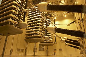
Thyristor valve stacks for Pole 2 of the HVDC Inter-Island between the North and South Islands of New Zealand. The man at the bottom gives scale to the size of the valves.
Each thyristor valve will typically contain tens or hundreds of thyristor levels, each operating at a different (high) potential with respect to earth. The command information to turn on the thyristors therefore cannot simply be sent using a wire connection – it needs to be isolated. The isolation method can be magnetic but is usually optical. Two optical methods are used: indirect and direct optical triggering. In the indirect optical triggering method, low-voltage control electronics send light pulses along optical fibres to the high-side control electronics, which derives its power from the voltage across each thyristor. The alternative direct optical triggering method dispenses with most of the high-side electronics, instead using light pulses from the control electronics to switch light-triggered thyristors (LTTs), although a small monitoring electronics unit may still be required for protection of the valve.
In a line-commutated converter, the DC current (usually) cannot change direction; it flows through a large inductance and can be considered almost constant. On the AC side, the converter behaves approximately as a current source, injecting both grid-frequency and harmonic currents into the AC network. For this reason, a line commutated converter for HVDC is also considered as a current-source inverter.
Voltage-sourced converters[edit]
Because thyristors can only be turned on (not off) by control action, the control system has only one degree of freedom – when to turn on the thyristor. This is an important limitation in some circumstances.
With some other types of semiconductor device such as the insulated-gate bipolar transistor (IGBT), both turn-on and turn-off can be controlled, giving a second degree of freedom. As a result, they can be used to make self-commutated converters. In such converters, the polarity of DC voltage is usually fixed and the DC voltage, being smoothed by a large capacitance, can be considered constant. For this reason, an HVDC converter using IGBTs is usually referred to as a voltage sourced converter. The additional controllability gives many advantages, notably the ability to switch the IGBTs on and off many times per cycle in order to improve the harmonic performance. Being self-commutated, the converter no longer relies on synchronous machines in the AC system for its operation. A voltage sourced converter can therefore feed power to an AC network consisting only of passive loads, something which is impossible with LCC HVDC.
HVDC systems based on voltage sourced converters normally use the six-pulse connection because the converter produces much less harmonic distortion than a comparable LCC and the twelve-pulse connection is unnecessary.
Most of the VSC HVDC systems built until 2012 were based on the two level converter, which can be thought of as a six pulse bridge in which the thyristors have been replaced by IGBTs with inverse-parallel diodes, and the DC smoothing reactors have been replaced by DC smoothing capacitors. Such converters derive their name from the discrete, two voltage levels at the AC output of each phase that correspond to the electrical potentials of the positive and negative DC terminals. Pulse-width modulation (PWM) is usually used to improve the harmonic distortion of the converter.
Some HVDC systems have been built with three level converters, but today most new VSC HVDC systems are being built with some form of multi-level converter, most commonly the Modular Multi-Level Converter (MMC), in which each valve consists of a number of independent converter submodules, each containing its own storage capacitor. The IGBTs in each submodule either bypass the capacitor or connect it into the circuit, allowing the valve to synthesize a stepped voltage with very low levels of harmonic distortion.
Converter transformers[edit]

A single-phase, three-winding converter transformer. The long valve-winding bushings, which project through the wall of the valve hall, are shown on the left. The line-winding bushing projects vertically upwards at centre-right
At the AC side of each converter, a bank of transformers, often three physically separated single-phase transformers, isolate the station from the AC supply, to provide a local earth, and to ensure the correct eventual DC voltage. The output of these transformers is then connected to the converter.
Converter transformers for LCC HVDC schemes are quite specialised because of the high levels of harmonic currents which flow through them, and because the secondary winding insulation experiences a permanent DC voltage, which affects the design of the insulating structure (valve side requires more solid insulation) inside the tank. In LCC systems, the transformer(s) also need to provide the 30° phase shift needed for harmonic cancellation.
Converter transformers for VSC HVDC systems are usually simpler and more conventional in design than those for LCC HVDC systems.
Reactive power[edit]
A major drawback of HVDC systems using line-commutated converters is that the converters inherently consume reactive power. The AC current flowing into the converter from the AC system lags behind the AC voltage so that, irrespective of the direction of active power flow, the converter always absorbs reactive power, behaving in the same way as a shunt reactor. The reactive power absorbed is at least 0.5 MVAr/MW under ideal conditions and can be higher than this when the converter is operating at higher than usual firing or extinction angle, or reduced DC voltage.
Although at HVDC converter stations connected directly to power stations some of the reactive power may be provided by the generators themselves, in most cases the reactive power consumed by the converter must be provided by banks of shunt capacitors connected at the AC terminals of the converter. The shunt capacitors are usually connected directly to the grid voltage but in some cases may be connected to a lower voltage via a tertiary winding on the converter transformer.
Since the reactive power consumed depends on the active power being transmitted, the shunt capacitors usually need to be subdivided into a number of switchable banks (typically 4 per converter) in order to prevent a surplus of reactive power being generated at low transmitted power.
The shunt capacitors are almost always provided with tuning reactors and, where necessary, damping resistors so that they can perform a dual role as harmonic filters.
Voltage-source converters, on the other hand, can either produce or consume reactive power on demand, with the result that usually no separate shunt capacitors are needed (other than those required purely for filtering).
Harmonics and filtering[edit]
All power electronic converters generate some degree of harmonic distortion on the AC and DC systems to which they are connected, and HVDC converters are no exception.
With the recently developed Modular Multi-Level Converter (MMC), levels of harmonic distortion may be practically negligible, but with line-commutated converters and simpler types of voltage-source converters, considerable harmonic distortion may be produced on both the AC and DC sides of the converter. As a result, harmonic filters are nearly always required at the AC terminals of such converters, and in HVDC transmission schemes using overhead lines, may also be required on the DC side.
Filters for line-commutated converters[edit]
The basic building-block of a line-commutated HVDC converter is the six-pulse bridge. This arrangement produces very high levels of harmonic distortion by acting as a current source injecting harmonic currents of order 6n±1 into the AC system and generating harmonic voltages of order 6n superimposed on the DC voltage.
It is very costly to provide harmonic filters capable of suppressing such harmonics, so a variant known as the twelve-pulse bridge (consisting of two six-pulse bridges in series with a 30° phase shift between them) is nearly always used. With the twelve-pulse arrangement, harmonics are still produced but only at orders 12n±1 on the AC side and 12n on the DC side. The task of suppressing such harmonics is still challenging, but manageable.
Line-commutated converters for HVDC are usually provided with combinations of harmonic filters designed to deal with the 11th and 13th harmonics on the AC side, and 12th harmonic on the DC side. Sometimes, high-pass filters may be provided to deal with 23rd, 25th, 35th, 37th... on the AC side and 24th, 36th... on the DC side. Sometimes, the AC filters may also need to provide damping at lower-order, non-characteristic harmonics such as 3rd or 5th harmonics.
The task of designing AC harmonic filters for HVDC converter stations is complex and computationally intensive, since in addition to ensuring that the converter does not produce an unacceptable level of voltage distortion on the AC system, it must be ensured that the harmonic filters do not resonate with some component elsewhere in the AC system. A detailed knowledge of the harmonic impedance of the AC system, at a wide range of frequencies, is needed in order to design the AC filters.[36]
DC filters are required only for HVDC transmission systems involving overhead lines. Voltage distortion is not a problem in its own right, since consumers do not connect directly to the DC terminals of the system, so the main design criterion for the DC filters is to ensure that the harmonic currents flowing in the DC lines do not induce interference in nearby open-wire telephone lines.[37] With the rise in digital mobile telecommunication systems, which are much less susceptible to interference, DC filters are becoming less important for HVDC systems.
Filters for voltage-sourced converters[edit]
Some types of voltage-sourced converters may produce such low levels of harmonic distortion that no filters are required at all. However, converter types such as the two-level converter, used with pulse-width modulation (PWM), still require some filtering, albeit less than on line-commutated converter systems.
With such converters, the harmonic spectrum is generally shifted to higher frequencies than with line-commutated converters. This usually allows the filter equipment to be smaller. The dominant harmonic frequencies are sidebands of the PWM frequency and multiples thereof. In HVDC applications, the PWM frequency is typically around 1–2 kHz.
Configurations[edit]
Monopole[edit]

Block diagram of a monopole system with earth return
In a common configuration, called monopole, one of the terminals of the rectifier is connected to earth ground. The other terminal, at a potential high above or below ground, is connected to a transmission line. The earthed terminal may be connected to the corresponding connection at the inverting station by means of a second conductor.
Monopole and earth return[edit]
If no metallic conductor is installed, current flows in the earth and/or sea between two specially designed earth electrodes. This arrangement is a type of single wire earth return system.
The electrodes are usually located some tens of kilometres from the stations and are connected to the stations via a medium-voltage electrode line. The design of the electrodes themselves depends on whether they are located on land, on the shore or at sea. For the monopolar configuration with earth return, the earth current flow is unidirectional, which means that the design of one of the electrodes (the cathode) can be relatively simple, although the design of anode electrode is quite complex.
For long-distance transmission, earth return can be considerably cheaper than alternatives using a dedicated neutral conductor, but it can lead to problems such as:
- Electrochemical corrosion of long buried metal objects such as pipelines
- Underwater earth-return electrodes in seawater may produce chlorine or otherwise affect water chemistry.
- An unbalanced current path may result in a net magnetic field, which can affect magnetic navigational compasses for ships passing over an underwater cable.
Monopole and metallic return[edit]
These effects can be eliminated with installation of a metallic return conductor between the two ends of the monopolar transmission line. Since one terminal of the converters is connected to earth, the return conductor need not be insulated for the full transmission voltage which makes it less costly than the high-voltage conductor. The decision of whether or not to use a metallic return conductor is based upon economic, technical and environmental factors.[38]
Modern monopolar systems for pure overhead lines carry typically 1.5 GW.[39] If underground or underwater cables are used, the typical value is 600 MW.
Most monopolar systems are designed for future bipolar expansion. Transmission line towers may be designed to carry two conductors, even if only one is used initially for the monopole transmission system. The second conductor is either unused, used as electrode line or connected in parallel with the other (as in case of Baltic Cable).
Symmetrical monopole[edit]
An alternative is to use two high-voltage conductors, operating at ± half of the DC voltage, with only a single converter at each end. In this arrangement, known as the symmetrical monopole, the converters are earthed only via a high impedance and there is no earth current. The symmetrical monopole arrangement is uncommon with line-commutated converters (the NorNed interconnection being a rare example) but is very common with Voltage Sourced Converters when cables are used.
Bipolar[edit]

Block diagram of a bipolar system that also has an earth return
In bipolar transmission a pair of conductors is used, each at a high potential with respect to ground, in opposite polarity. Since these conductors must be insulated for the full voltage, transmission line cost is higher than a monopole with a return conductor. However, there are a number of advantages to bipolar transmission which can make it an attractive option.
- Under normal load, negligible earth-current flows, as in the case of monopolar transmission with a metallic earth-return. This reduces earth return loss and environmental effects.
- When a fault develops in a line, with earth return electrodes installed at each end of the line, approximately half the rated power can continue to flow using the earth as a return path, operating in monopolar mode.
- Since for a given total power rating each conductor of a bipolar line carries only half the current of monopolar lines, the cost of the second conductor is reduced compared to a monopolar line of the same rating.
- In very adverse terrain, the second conductor may be carried on an independent set of transmission towers, so that some power may continue to be transmitted even if one line is damaged.
A bipolar system may also be installed with a metallic earth return conductor.
Bipolar systems may carry as much as 4 GW at voltages of ±660 kV with a single converter per pole, as on the Ningdong–Shandong project in China. With a power rating of 2000 MW per twelve-pulse converter, the converters for that project were (as of 2010) the most powerful HVDC converters ever built.[40] Even higher powers can be achieved by connecting two or more twelve-pulse converters in series in each pole, as is used in the ±800 kV Xiangjiaba–Shanghai project in China, which uses two twelve-pulse converter bridges in each pole, each rated at 400 kV DC and 1600 MW.
Submarine cable installations initially commissioned as a monopole may be upgraded with additional cables and operated as a bipole.

A block diagram of a bipolar HVDC transmission system, between two stations designated A and B. AC – represents an alternating current network CON – represents a converter valve, either rectifier or inverter, TR represents a power transformer, DCTL is the direct-current transmission line conductor, DCL is a direct-current filter inductor, BP represents a bypass switch, and PM represent power factor correction and harmonic filter networks required at both ends of the link. The DC transmission line may be very short in a back-to-back link, or extend hundreds of miles (km) overhead, underground or underwater. One conductor of the DC line may be replaced by connections to earth ground.
A bipolar scheme can be implemented so that the polarity of one or both poles can be changed. This allows the operation as two parallel monopoles. If one conductor fails, transmission can still continue at reduced capacity. Losses may increase if ground electrodes and lines are not designed for the extra current in this mode. To reduce losses in this case, intermediate switching stations may be installed, at which line segments can be switched off or parallelized. This was done at Inga–Shaba HVDC.
Back to back[edit]
A back-to-back station (or B2B for short) is a plant in which both converters are in the same area, usually in the same building. The length of the direct current line is kept as short as possible. HVDC back-to-back stations are used for
The DC voltage in the intermediate circuit can be selected freely at HVDC back-to-back stations because of the short conductor length. The DC voltage is usually selected to be as low as possible, in order to build a small valve hall and to reduce the number of thyristors connected in series in each valve. For this reason, at HVDC back-to-back stations, valves with the highest available current rating (in some cases, up to 4,500 A) used.
Multi-terminal systems[edit]
The most common configuration of an HVDC link consists of two converter stations connected by an overhead power line or undersea cable.
Multi-terminal HVDC links, connecting more than two points, are rare. The configuration of multiple terminals can be series, parallel, or hybrid (a mixture of series and parallel). Parallel configuration tends to be used for large capacity stations, and series for lower capacity stations. An example is the 2,000 MW Quebec - New England Transmission system opened in 1992, which is currently the largest multi-terminal HVDC system in the world.[41]
Multi-terminal systems are difficult to realise using line commutated converters because reversals of power are effected by reversing the polarity of DC voltage, which affects all converters connected to the system. With Voltage Sourced Converters, power reversal is achieved instead by reversing the direction of current, making parallel-connected multi-terminals systems much easier to control. For this reason, multi-terminal systems are expected to become much more common in the near future.
China is expanding its grid to keep up with increased power demand, while addressing environmental targets. China Southern Power Grid started a three terminals VSC HVDC pilot project in 2011. The project has designed ratings of ±160kV/200MW-100MW-50MW and will be used to bring wind power generated on Nanao island into the mainland Guangdong power grid through 32 km of combination of HVDC land cables, sea cables and overhead lines. This project was put into operation on December 19, 2013.[42]
In India, the multiterminal North-East Agra project is planned for commissioning in 2016. It will be rated 8000 MW, 800 kV using four bipolar lines, and will transmit power from two converter stations in the east to a converter at Agra, a distance of 1728 km.[43]
Tripole[edit]
A scheme patented in 2004[44] is intended for conversion of existing AC transmission lines to HVDC. Two of the three circuit conductors are operated as a bipole. The third conductor is used as a parallel monopole, equipped with reversing valves (or parallel valves connected in reverse polarity). The parallel monopole periodically relieves current from one pole or the other, switching polarity over a span of several minutes. The bipole conductors would be loaded to either 1.37 or 0.37 of their thermal limit, with the parallel monopole always carrying ±1 times its thermal limit current. The combined RMS heating effect is as if each of the conductors is always carrying 1.0 of its rated current. This allows heavier currents to be carried by the bipole conductors, and full use of the installed third conductor for energy transmission. High currents can be circulated through the line conductors even when load demand is low, for removal of ice.
As of 2012[update], no tri-pole conversions are in operation, although a transmission line in India has been converted to bipole HVDC ( HVDC Sileru-Barsoor).
Other arrangements[edit]
Cross-Skagerrak consists of 3 poles, from which 2 are switched in parallel and the third uses an opposite polarity with a higher transmission voltage. A similar arrangement was the HVDC Inter-Island in New Zealand after a capacity upgrade in 1992, in which the two original converters (using mercury-arc valves) were parallel-switched feeding the same pole and a new third (thyristor) converter installed with opposite polarity and higher operation voltage. This configuration ended in 2012 when the two old converters were replaced with a single, new, thyristor converter.
Corona discharge[edit]
Corona discharge is the creation of ions in a fluid (such as air) by the presence of a strong electric field. Electrons are torn from neutral air, and either the positive ions or the electrons are attracted to the conductor, while the charged particles drift. This effect can cause considerable power loss, create audible and radio-frequency interference, generate toxic compounds such as oxides of nitrogen and ozone, and bring forth arcing.
Both AC and DC transmission lines can generate coronas, in the former case in the form of oscillating particles, in the latter a constant wind. Due to the space charge formed around the conductors, an HVDC system may have about half the loss per unit length of a high voltage AC system carrying the same amount of power. With monopolar transmission the choice of polarity of the energized conductor leads to a degree of control over the corona discharge. In particular, the polarity of the ions emitted can be controlled, which may have an environmental impact on ozone creation. Negative coronas generate considerably more ozone than positive coronas, and generate it further downwind of the power line, creating the potential for health effects. The use of a positive voltage will reduce the ozone impacts of monopole HVDC power lines.
Applications[edit]
Overview[edit]
The controllability of a current-flow through HVDC rectifiers and inverters, their application in connecting unsynchronized networks, and their applications in efficient submarine cables mean that HVDC interconnections are often used at national or regional boundaries for the exchange of power (in North America, HVDC connections divide much of Canada and the United States into several electrical regions that cross national borders, although the purpose of these connections is still to connect unsynchronized AC grids to each other). Offshore windfarms also require undersea cables, and their turbines are unsynchronized. In very long-distance connections between two locations, such as power transmission from a large hydroelectric power plant at a remote site to an urban area, HVDC transmission systems may appropriately be used; several schemes of these kind have been built. For interconnections to Siberia, Canada, and the Scandinavian North, the decreased line-costs of HVDC also make it applicable, see List of HVDC projects. Other applications are noted throughout this article.
AC network interconnections[edit]
AC transmission lines can interconnect only synchronized AC networks with the same frequency with limits on the allowable phase difference between the two ends of the line. Many areas that wish to share power have unsynchronized networks. The power grids of the UK, Northern Europe and continental Europe are not united into a single synchronized network. Japan has 50 Hz and 60 Hz networks. Continental North America, while operating at 60 Hz throughout, is divided into regions which are unsynchronised: East, West, Texas, Quebec, and Alaska. Brazil and Paraguay, which share the enormous Itaipu Dam hydroelectric plant, operate on 60 Hz and 50 Hz respectively. However, HVDC systems make it possible to interconnect unsynchronized AC networks, and also add the possibility of controlling AC voltage and reactive power flow.
A generator connected to a long AC transmission line may become unstable and fall out of synchronization with a distant AC power system. An HVDC transmission link may make it economically feasible to use remote generation sites. Wind farms located off-shore may use HVDC systems to collect power from multiple unsynchronized generators for transmission to the shore by an underwater cable.[45]
In general, however, an HVDC power line will interconnect two AC regions of the power-distribution grid. Machinery to convert between AC and DC power adds a considerable cost in power transmission. The conversion from AC to DC is known as rectification, and from DC to AC as inversion. Above a certain break-even distance (about 50 km for submarine cables, and perhaps 600–800 km for overhead cables), the lower cost of the HVDC electrical conductors outweighs the cost of the electronics.
The conversion electronics also present an opportunity to effectively manage the power grid by means of controlling the magnitude and direction of power flow. An additional advantage of the existence of HVDC links, therefore, is potential increased stability in the transmission grid.
Renewable electricity superhighways[edit]

Two HVDC lines cross near Wing, North Dakota.
A number of studies have highlighted the potential benefits of very wide area super grids based on HVDC since they can mitigate the effects of intermittency by averaging and smoothing the outputs of large numbers of geographically dispersed wind farms or solar farms.[46] Czisch's study concludes that a grid covering the fringes of Europe could bring 100% renewable power (70% wind, 30% biomass) at close to today's prices. There has been debate over the technical feasibility of this proposal[47] and the political risks involved in energy transmission across a large number of international borders.[48]
The construction of such green power superhighways is advocated in a white paper that was released by the American Wind Energy Association and the Solar Energy Industries Association in 2009.[49] Clean Line Energy Partners is developing four HVDC lines in the U.S. for long distance electric power transmission.[50]
In January 2009, the European Commission proposed €300 million to subsidize the development of HVDC links between Ireland, Britain, the Netherlands, Germany, Denmark, and Sweden, as part of a wider €1.2 billion package supporting links to offshore wind farms and cross-border interconnectors throughout Europe. Meanwhile, the recently founded Union of the Mediterranean has embraced a Mediterranean Solar Plan to import large amounts of concentrating solar power into Europe from North Africa and the Middle East.[51]


